

How To Load The Period Register For Timer Counter Atmel Atxmega128a1u
Contents
- 1 Nuts
- 2 Timer 0 Basics
- 3 Timer 0 Example
- 3.ane Code
- 4 Timer 1 Nuts
- five Timer 1 Example
- 5.1 Code
- 6 Timer 2
- 7 Downloads
Basics
Timers come in handy when you want to set some time interval like your warning. This tin exist very precise to a few microseconds.

Timers/Counters are essential part of any mod MCU. Recollect it is the same hardware unit inside the MCU that is used either as Timers or Counter. Timers/counters are an independent unit within a micro-controller. They basically run independently of what job CPU is performing. Hence they come in very handy, and are primarily used for the following:
- Internal Timer: Every bit an internal timer the unit, ticks on the oscillator frequency. The oscillator frequency tin can be directly feed to the timer or it can be pre-scaled. In this mode it used generate precise delays. Or as precise fourth dimension counting machine.
- External Counter: In this way the unit is used to count events on a specific external pivot on a MCU.
- Pulse width Modulation(PWM) Generator: PWM is used in speed command of motors and various other applications.
Atmega32 has 3 timer units, timer 0, timer i and timer 2 respectively. Permit us start our exploration with timer 0.
Timer 0 Basics
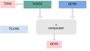
 Timer 0 is a 8 flake timer. It basically means it can count from 0 to 2^8 255. The operation of timer 0 is straight frontward. The TCNT0 register hold the timer Count and it is incremented on every timer "tick". If the timer is turned on information technology ticks from 0 to 255 and overflows. If information technology does so, a Timer OverFlow Flag(TOV) is fix.
You tin can as well load a count value in TCNT0 and starting time the timer from a specific count. Another interesting feature is that a value tin exist prepare in the Output Compare Register (OCR0), and whenever TCNT0 reaches that value, the Output Compare Flag (OCF0) flag is Set.
| TCNT0 | |||||||
|---|---|---|---|---|---|---|---|
| D7 | D6 | D5 | D4 | D3 | D2 | D1 | D0 |
The configuration of the Timer can be set using the TCCR0 register shown below. With this you tin can basically select 2 things:
- The Frequency of the Clock Source with CS02, CS01, CS00 bits.
- The mode of the timer. For the first example we will use information technology in normal mode where it ticks from zero to the highest value(255)
| TCCR0 | |||||||
|---|---|---|---|---|---|---|---|
| D7 | D6 | D5 | D4 | D3 | D2 | D1 | D0 |
| FOC0 | WGM00 | COM01 | COM00 | WGM01 | CS02 | CS01 | CS00 |
| D2 | D1 | D0 | Clock Source |
|---|---|---|---|
| CS02 | CS01 | CS00 | Freq |
| 0 | 0 | 0 | No Clock (Stopped) |
| 0 | 0 | 1 | Clk |
| 0 | 1 | 0 | Clk/8 |
| 0 | 1 | i | Clk/64 |
| 1 | 0 | 0 | Clk/256 |
| ane | 0 | one | Clk/1024 |
| i | i | 0 | Clk/T0-Falling edge |
| ane | 1 | 1 | Clk/T0-Rising Edge |
| D6 | D3 | PWM |
|---|---|---|
| WGM00 | WGM01 | Way |
| 0 | 0 | Normal |
| 0 | 1 | CTC (Clear timer on compare match) |
| 1 | 0 | PWM (Phase correct) |
| i | 1 | Fast PWM |
The Timer/counter Interrupt Flag Register(TIFR) holds the two basic flags we demand the TOV and OVF. Other $.25 correspond to the timer interrupts, which we will expect at in some other tutorial.
| TIFR | |||||||
|---|---|---|---|---|---|---|---|
| D7 | D6 | D5 | D4 | D3 | D2 | D1 | D0 |
| OCF2 | TOV2 | ICF1 | OCF1A | OCF1B | TOV1 | OCF0 | TOV0 |
Timer 0 Instance
Toggle LED connected to PD4 every 100msec using Timer Cipher with 1024 pre-scalar in normal mode.
What is the Max delay Timer 0 overflow generates? Okay, lets calculate. The Explore Ultra AVR dev lath comes with a 16MHz on board crystal and the fuse bits are ready appropriately. If we use the highest pre-scalar of 1024, calculation shows it can generate a delay of 16milli seconds every time timer zero overflows.
$$Ftimer = CPU Frequency/Prescalar $$ $$Ftimer = 16MHz/1024 = 15.625KHz $$ $$Ttick = 1/ fifteen.625K = 64 \mu seconds$$ $$Ttotal = 64\mu due south X 255 = 16ms$$
Of-course 16ms is non enough, so the side by side obvious question is:
How many times should the timer overflow to generate a delay of approximately 100msec?
$$ OverFlowCount = 100ms/16ms = half dozen.25 ≈ six $$
Now let's write a elementary program which will toggle a port pin (PD4) after the timer 0 overflows 6 times.
- Load TCNT0 with 0x00
- Set CS00 and CS02 bits in TCCR0 register. This will starting time the timeWe will calculate the tick time in merely a moment.r at Clk/1024 speed.
- Monitor the TOV0 flag in the TIFR0 register to check if the timer has over-flowed, keep a timerOverFlowCount.
- If timerOverFlowCount >= 6, toggle the led on PD4 and reset the count
Code
Timer 1 Basics
The Timer 1 is 16 chip, that means it can count from 0 to $$2^{16} = 65536$$. Hence the Timer/Counter 1 is a 16 fleck registered formed out of TCNT1H and TCNT1L equally shown below.
| TCNT1H | TCNT1L | ||||||||||||||
|---|---|---|---|---|---|---|---|---|---|---|---|---|---|---|---|
| D15 | D14 | D13 | D12 | D11 | D10 | D9 | D8 | D7 | D6 | D5 | D4 | D3 | D2 | D1 | D0 |
Timer three also has ii control registers which allow united states of america to configure it and utilize information technology in whatsoever mode you wish.
| TCCR1A | |||||||
|---|---|---|---|---|---|---|---|
| D7 | D6 | D5 | D4 | D3 | D2 | D1 | D0 |
| COM1A1 | COM1A0 | COM1B1 | COM1B0 | FOC1A | FOC1B | WGM11 | WGM10 |
| TCCR1B | |||||||
|---|---|---|---|---|---|---|---|
| D7 | D6 | D5 | D4 | D3 | D2 | D1 | D0 |
| ICNC1 | ICES1 | - | WGM13 | WGM12 | CS12 | CS11 | CS10 |
| D2 | D1 | D0 | Clock Source |
|---|---|---|---|
| CS12 | CS11 | CS10 | Freq |
| 0 | 0 | 0 | No Clock (Stopped) |
| 0 | 0 | 1 | Clk |
| 0 | 1 | 0 | Clk/eight |
| 0 | 1 | i | Clk/64 |
| 1 | 0 | 0 | Clk/256 |
| 1 | 0 | i | Clk/1024 |
| 1 | 1 | 0 | Clk/T1-Falling edge |
| one | 1 | ane | Clk/T1-Rising Edge |
Yes, and indeed nosotros take a Flag register which will tell us the status of Timer 1 equally shown beneath.
| TIFR | |||||||
|---|---|---|---|---|---|---|---|
| D7 | D6 | D5 | D4 | D3 | D2 | D1 | D0 |
| OCF2 | TOV2 | ICF1 | OCF1A | OCF1B | TOV1 | OCF0 | TOV0 |
Timer i Instance
Let us repeat the case of Timer 0 of toggling PD4 every 100ms. This time since it is a 16 bit timer, let's see what is the max delay information technology generates with a pre-scalar of 1024.
$$Ftimer = CPU Frequency/Prescalar $$ $$Ftimer = 16MHz/1024 = xv.625KHz $$ $$Ttick = 1/ fifteen.625K = 64 \mu seconds$$ $$Ttotal = 64\mu due south X 65536 = 4 seconds$$
So that is 4 secs! We just need 100 msec so, $$100ms/64\mu s = 1562 = 0x061A$$
This time, instead of using the overflow flag, it's use Output Compare Register (OCR) and the related flag.
So the with the following steps we should be able to generate the required delay.
- Load OCR1H with 0x3d and OCR1L with 0x09
- Run the timer with pre-scalar of 1024 by setting CS12 and CS10 $.25.
- Monitor OCF flag and if it is set, toggle the led
- Reset the TCNT1L and TCNT1H values to goose egg and repeat steps i to 3.
Code
Timer two
Well, timer 2 is pretty similar to the timers covered above. Give it a shot, should you've any questions do comment below.
Timers are independent units from the CPU. Hence if we employ timers with Interrupts it can brand the CPU free from polling the flags every-time. This is the way they are used normally. Check AVR Timer Interrupts tutorial where we volition comprehend all of that.
Downloads
Download the complete project folder from the beneath link: https://github.com/ExploreEmbedded/ATmega32_ExploreUltraAvrDevKit/archive/master.zip
Have a opinion, suggestion , question or feedback about the article allow information technology out here!

How To Load The Period Register For Timer Counter Atmel Atxmega128a1u,
Source: https://exploreembedded.com/wiki/AVR_Timer_programming
Posted by: berrymasul1992.blogspot.com
0 Response to "How To Load The Period Register For Timer Counter Atmel Atxmega128a1u"
Post a Comment